My old Ryobi RBL1802LIXA leaf blower’s impeller died after many years of good service. Unfortunately being an older model, Ryobi no longer sell a replacement part.
Rather than throwing away an otherwise good leaf blower, I decided to fabricate a replacement impeller with my 3D printer. As the old impeller was still in good enough shape to enable measurements to be made, it was fairly easy to re-create it using Lightwave 3D, from which the 3D print files could be produced.
As I only had PLA plastic at the time, I took a bit of a gamble as to whether a PLA 3D printed part would be strong enough. Otherwise, I would have switched to ABS. However, the PLA print has proved to be fine over many months of using the refurbished leaf blower.
Initial attempt
With the first Lightwave 3D design I tried to print the whole unit as a single piece, but it wasn’t possible to remove all the support material, so a re-think became necessary.
Multi-part redesign
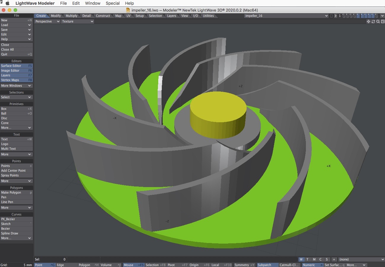
The redesign was a multi-piece PLA part that could be glued together with SuperGlue.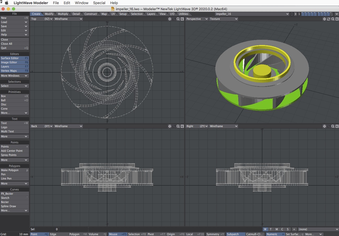
The base part (shown in green) and vanes were designed to all be printed as a single unit; a circular top was to be glued on to the vanes. The motor shaft mount in the centre (shown as yellow with a grey collar) is also a separate part designed to protrude through the base and glued into place. The motor shaft mount, vanes and base could have been printed as a single piece. However, because the motor shaft protrudes through a hole in the base, there would have been a lot of support material to be removed. It was just easier to do it as separate pieces, and the combination of SuperGlue and baking soda (see below) meant there would not be any loss in strength.
After abandoning trying to produce the whole impeller as a single printed piece, I tried producing the top part with curved recessed vane slots, but this proved too difficult to fit together, and the recesses compromised the strength of the part.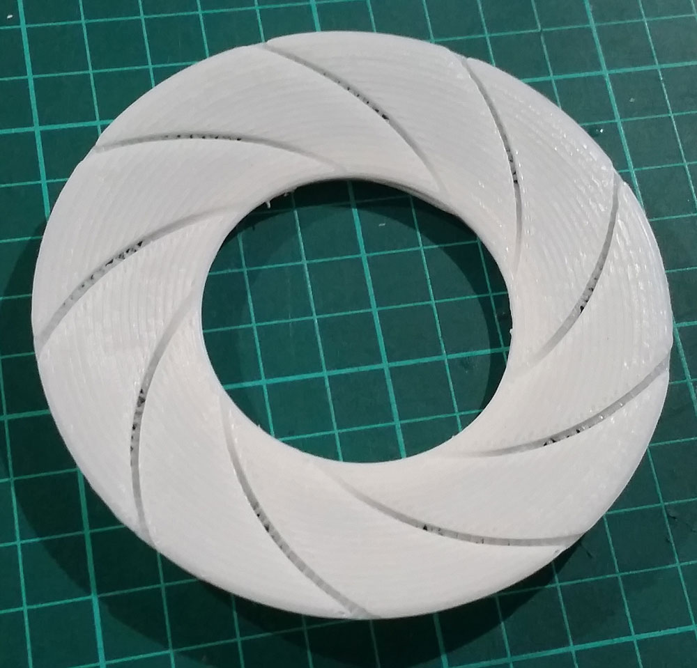
Instead, what turned out to be a better idea was to dispense with the recessed curved vane slots and add small raised vane guides to the top part. Note in the screen grab below, a series of small triangular raised guides have been added around the periphery of the top part, shown here upside down. The vanes will be 3D printed along with the base (not shown here) as a single piece. As a bonus, this method makes the vanes self-catering when positioning with the top piece for gluing.

3D Printing and assembly
The various 3D printed components (clockwise from bottom left):
- top
- top collar alignment jig (to be removed after use)
- top collar (to be glued to the upperside of the top)
- motor shaft mount (which will protrude through the holes in the base and bottom collar)
- bottom collar (to be glued to the underside of the base)
- base and vanes
When gluing, care had to be taken as not to stick the alignment jig!

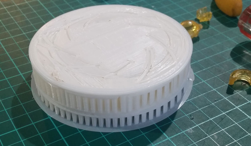
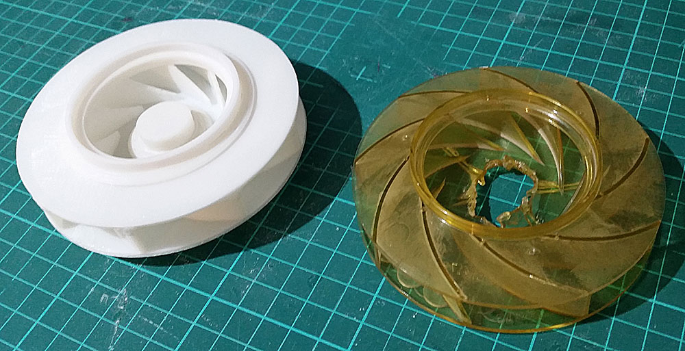
Assembled 3D printed PLA replacement part with the original polycarbonate part which was damaged when its motor mount tore apart following many years of use. Other than that, this blower has been, and still is, a great unit.
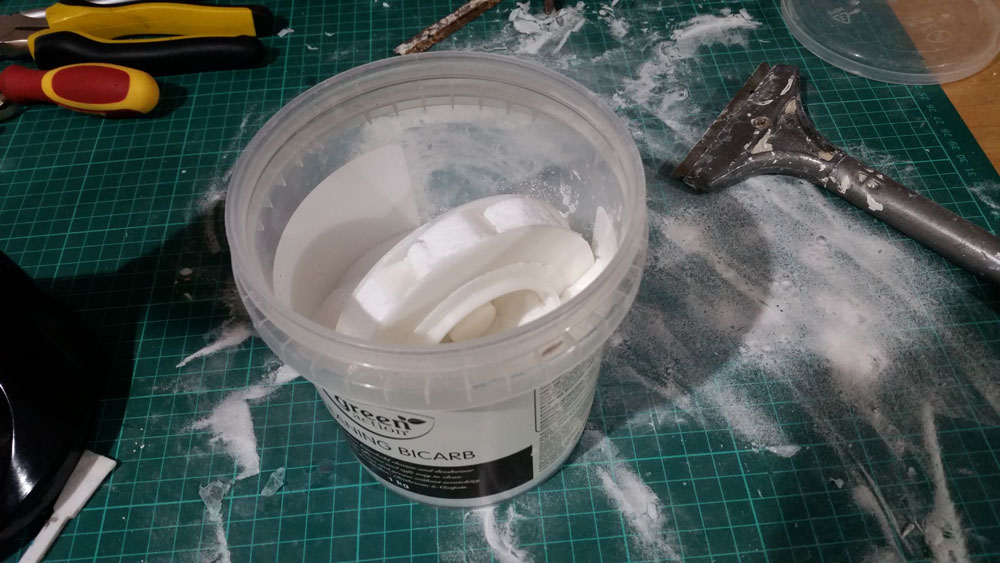
The gluing process was greatly speeded up by plunging freshly glued components into a tub of baking soda (bi-carb). SuperGlue and baking soda set hard almost instantly. This meant that instead of having to hold, tape or clamp pieces together for several minutes while waiting for the glue to set, I only had to hold the pieces together for a few seconds, and any excess glue that had oozed out from the joins set off like rock, greatly increasing the strength of the overall part. Any excess baking soda was swept up or brushed off back into the tub.
Fitting the new part
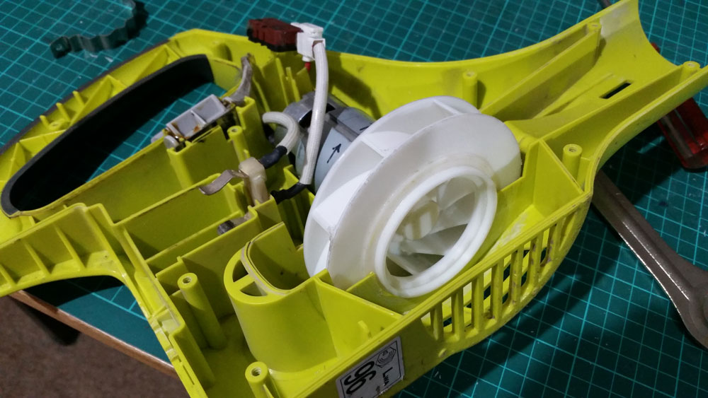
The top of the replacement impeller was designed to sit into the green housing with a bit less than 1mm clearance to enable free rotation whilst maintaining adequate air pressure.
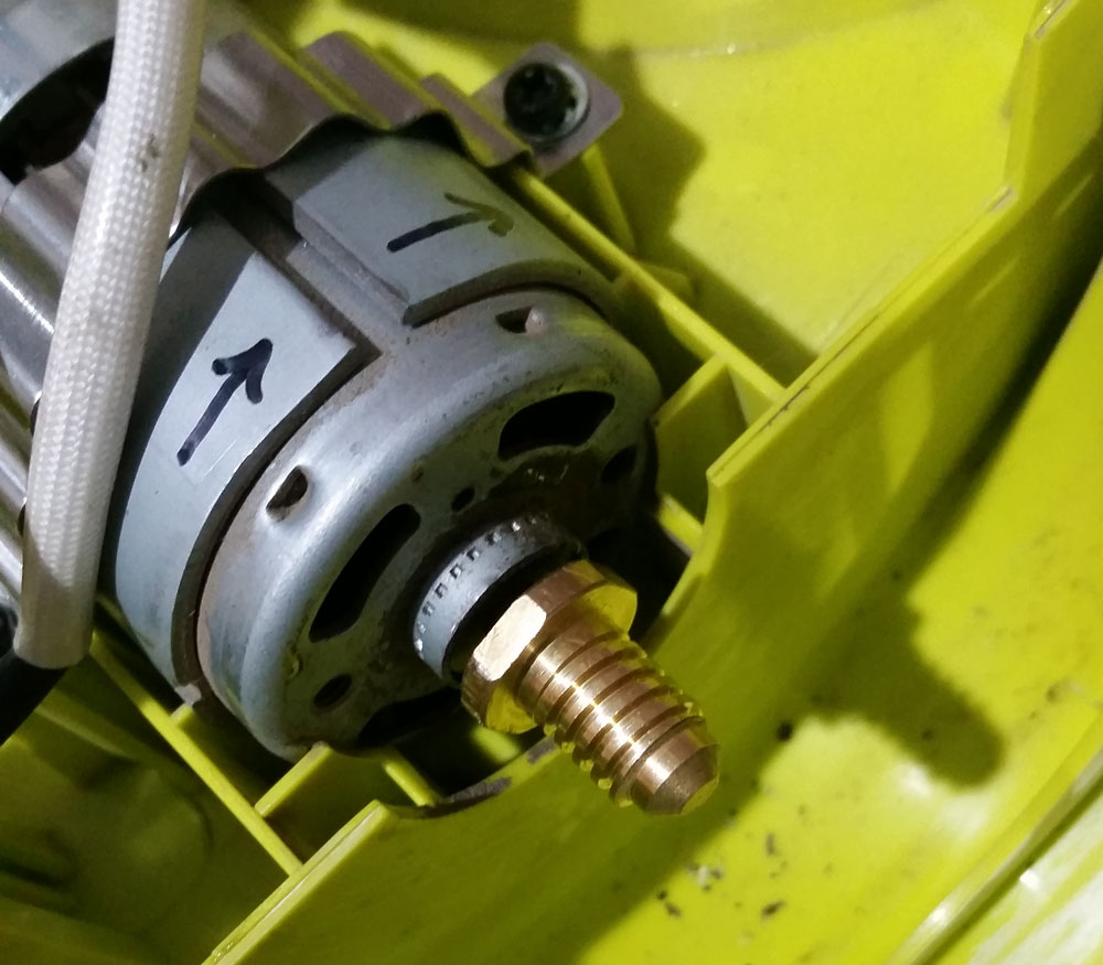
The initial design of the impeller motor mount was to have hole with a thread to match that of the motor’s brass shaft, but using a purpose-printed motor mount as a test-piece revealed that alignment and fit was too difficult.
An easier solution was to design the mount hole without a thread, designing its diameter to be a tight fit over the motor shaft. The brass shaft was heated with a butane torch so the motor mount could be pushed over it and seated firmly in place.
Care had to be taken to heat the brass shaft only as hot as necessary whilst making sure that it wasn’t too cold, otherwise the motor mount would not have gone on all the way. If the motor mount wasn’t seated correctly on the first attempt, removal would not have been possible without destroying the plastic, so another complete impeller would have to been printed. Fortunately it went on to the motor shaft correctly on the first attempt!

Although the impeller and blower housing are designed not to touch, just for an extra level of ‘peace of mind’, both the impeller top collar and housing mount were smeared with grease. This precaution may be unnecessary, as there has been no indication of rubbing over several months of use – no burning smell, excessive noise or deformed plastic. So far, so good!